Difference between revisions of "Modeler:12/DiagramDesigner"
m (→Selecting) |
m (→Selecting) |
||
| Line 14: | Line 14: | ||
# '''Select a Role'''. Using Alt while clicking a single Role for reordering during dragging. (This only works in versions before 9.6. After that version roles are automatically positioned depending on the PlayedByOT part. The position can be changed using the relative positioning of the PlayedByOT parts, or by inserting a breakpoint in that line going out.) | # '''Select a Role'''. Using Alt while clicking a single Role for reordering during dragging. (This only works in versions before 9.6. After that version roles are automatically positioned depending on the PlayedByOT part. The position can be changed using the relative positioning of the PlayedByOT parts, or by inserting a breakpoint in that line going out.) | ||
=== Keyboard Control === | |||
''(v12.6+)'' | |||
* A focus is on one element at a time. | * A focus is on one element at a time. | ||
* The focused item can be toggle in and out of the total selection using the '''Spacebar'''. | * The focused item can be toggle in and out of the total selection using the '''Spacebar'''. | ||
Latest revision as of 07:18, 3 December 2022
Diagram Designer Window
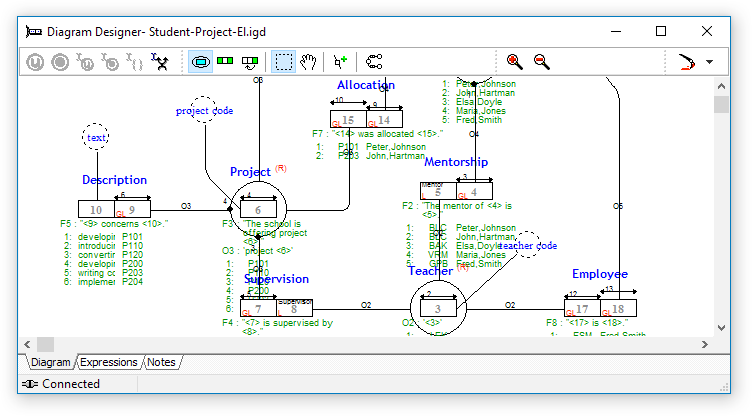
This window allows a visual feedback of the model stored in the repository. Adding or removing objects from this diagram does not influence the model.
Diagram
You may easily switch the diagram to different visual styles and setup by using the brush button on the top-right. It shows a menu to save, load or alter the options. Once you've setup several styles, you can use this same menu to switch styles.
Selecting
Fact Types can be dragged into a diagram from the repository using the mouse. Selections inside the diagram itself can be made using the three different selection modi (Ctl + 1,2,3):
- Select OTFT. Use Shift while clicking to toggle individual OTFT's
- Select Role. Use Ctrl while clicking to toggles individual Roles
- Select a Role. Using Alt while clicking a single Role for reordering during dragging. (This only works in versions before 9.6. After that version roles are automatically positioned depending on the PlayedByOT part. The position can be changed using the relative positioning of the PlayedByOT parts, or by inserting a breakpoint in that line going out.)
Keyboard Control
(v12.6+)
- A focus is on one element at a time.
- The focused item can be toggle in and out of the total selection using the Spacebar.
- The focused item can be changed using mouse or arrows on the keyboard.
- The selection can be moved with Alt+Arrows on the keyboard.
- The shapes and images can be resized using Shift+Arrows.
- Pressing Escape brings the focus to any outlining container, group or shape.
- Scrolling with the (Shift+) mouse scrollwheel is now possible.
- The focused item can be moved directly using Alt+Shift+Arrow.
Styles
The visual properties for the diagram can be altered quickly using styles. The Diagram options can be adjusted per style, and the styles are changeable using the button with the paintbrush icon.
It shows a popup menu to edit the options, save the current style, or choose one of the existing styles as previously saved. The special style called 'Default' will be used for new diagrams.
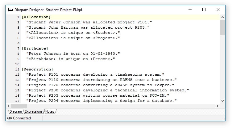
Expressions
All objects visualized in the diagram contain verbalizations which are shown here.

Hint: Try doubleclicking the lines and type names. They'll result in model navigation.
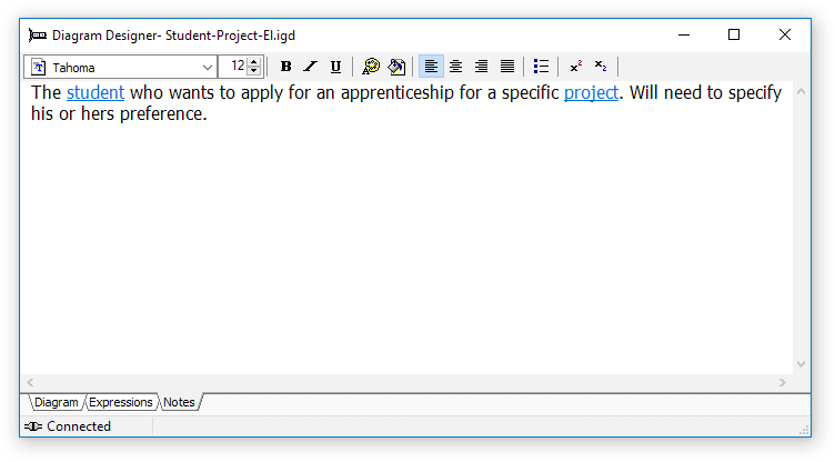
Notes
This tab allows rich text to be entered where recognized words are hi-lighted. The words recognized may be a name of a diagram or fact types. This automagic linking happens without any intervention. Name changes in the project or model may remove or add links.
The hyperlinks will be automatically created by CaseTalk. It may link to matching diagram names or type names in the model. A click on such a hyperlink will navigate you to the matched item.
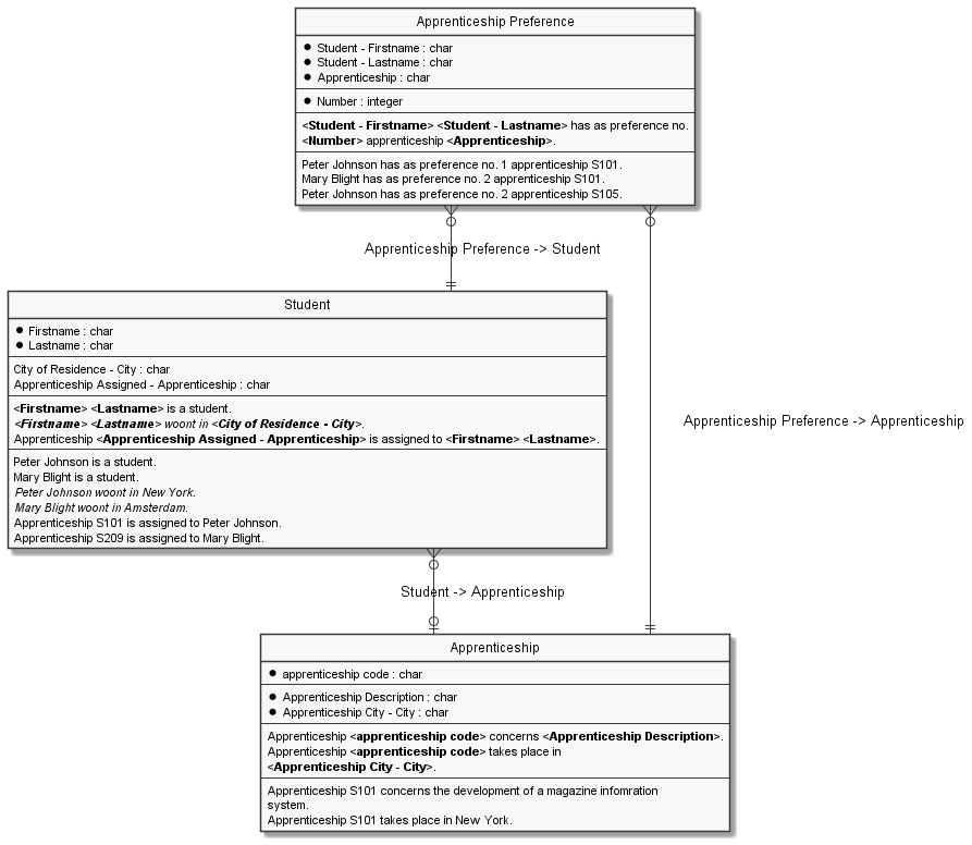
ERD, UML and Concept Map
Since CaseTalk 12.2 the model transformation (GLR) will result in an additional tab called ERD. This will automatically render a ER Diagram matching the content of the diagram. Below is an example how that may render. Java is required (See Installation).
While modeling and the Advanced Tools Preferences are set to Parallel Validation the model can automagically generate UML and Concept Maps as well.


